Dec 15, 2023
Colonial Solar House
A Net-Positive Energy Retrofit in the Heartland
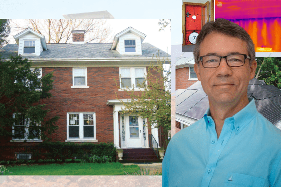
By: Scott Willenbrock
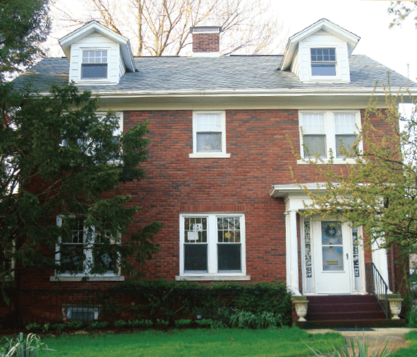
Some years ago, I became concerned about the future impacts of climate change. The dominant cause of greenhouse gas emissions is mankind’s use of energy, so I began to learn about energy efficiency and renewable energy. I heard a presentation from a colleague of mine at the University of Illinois at Urbana-Champaign, Ty Newell, about a net-positive energy house that he had designed and built in 2010, dubbed Equinox House. He described that the walls contain 12 inches of insulating foam, that the house is tightly sealed, that all heating and cooling is done with small air-source heat pumps, and that the entire house, plus the local driving of an electric vehicle, is powered by a modest-sized (8.2 kW) solar array. It was extremely impressive but left me feeling despondent about my own 1929 colonial-style house. How could I even come close to what he had achieved? My wood-framed, brick house provided a pleasant home for a family of four, but it was an energy hog.
I describe below how I was able to retrofit my house, dubbed Colonial Solar House, to provide all its own energy, plus enough energy to power the local driving of not one, but two electric vehicles. The house has been operating like this for over 5 years now, so it is a good time to take stock of what has worked well and what could have been done better. I am a physics professor, not a home energy professional, but I was fortunate to get help from many experts in my community.
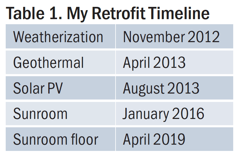
The logic to creating a net-positive energy home is to install enough solar photovoltaic modules to power the house and cars, to convert everything in the house to run on electricity, and to make everything as efficient as possible. I actually did the work in the reverse order, but I will describe the retrofit of the house in the logical order (see Table 1).
Solar Photovoltaics
These days there are several good companies that install solar photovoltaics at a reasonable price in central Illinois, but that was not the case in 2013. I didn’t even harbor the idea of doing it myself until I saw the DIY job of Phil Krein, a colleague of mine. It didn’t look to be beyond my meager capabilities. My training is in theoretical particle physics, and I am not particularly handy with tools. Fortunately, my brother Mark is very handy, and just a phone call away. I also got a lot of good advice from John Hammons, from whom I purchased everything I needed for my solar array.
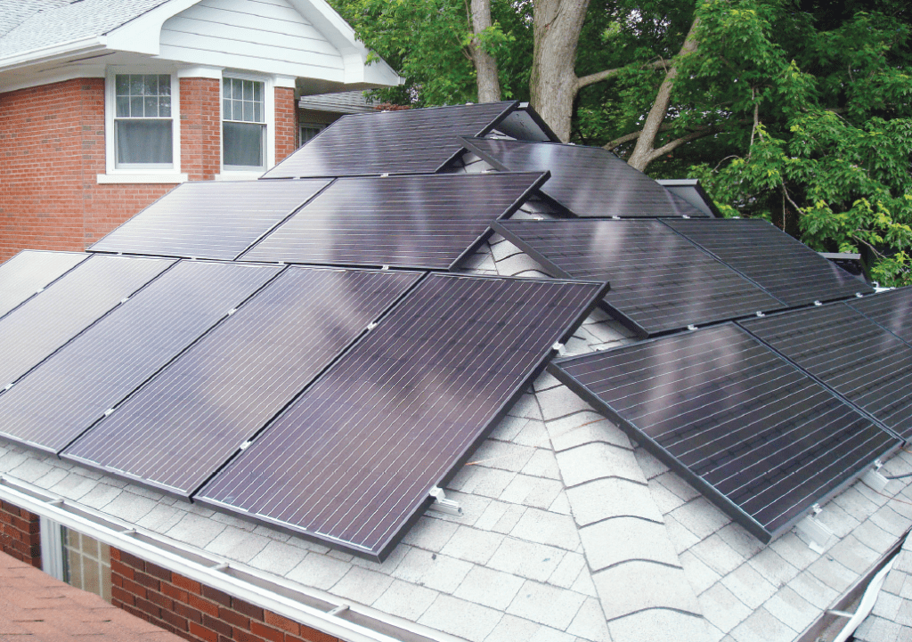
The modules that Phil Krein installed, and that I ended up using as well, have microinverters attached to the back. These particular microinverters were developed by Phil and Pat Chapman, a former colleague, who founded SolarBridge Technologies, which was later acquired by SunPower and then Enphase Energy. The microinverters presented several advantages over the more usual string inverter. Most importantly, they allow each module to operate independently of its neighbors, so if one module is shaded, it does not affect the others. This is crucial for my array, as I live in an old part of town with lots of mature trees, and I do suffer shading at various times of the day. Second, the microinverters made the electrical work trivial. All I needed to do was insert a plug from one module into the receptacle of its neighbor. I hired an electrician to make the final connection of the array to the grid. Third, each module reports its production information to a data logger that I can access from the internet, so I can keep an eye on the modules to see if there are any problems. Thus far there have not been any. A fourth advantage is that the microinverters (as well as the modules themselves) are warrantied for 25 years, while a string inverter typically needs to be replaced after about 10 years.
I first installed modules on my garage, which has a hip roof and thus presents an interesting geometry challenge. The south-facing modules are ideally oriented, with a tilt angle of 30 degrees. The east- and west-facing modules, while not ideal, still produce about 80% of the energy of the south-facing modules over the course of the year. You can model this easily using the online tool provided by the National Renewable Energy Laboratory (NREL), PVWatts. (See below for the link to this tool.) There are also several low-tilt modules on two sheds behind the garage, bringing the total number of modules to 28 (7.1 kW). This array would be about the right size to provide most of the electricity for a house that is heated with natural gas, as mine was. However, I need a much larger array to heat with electricity (via a geothermal heat pump) and to provide energy for two electric vehicles.
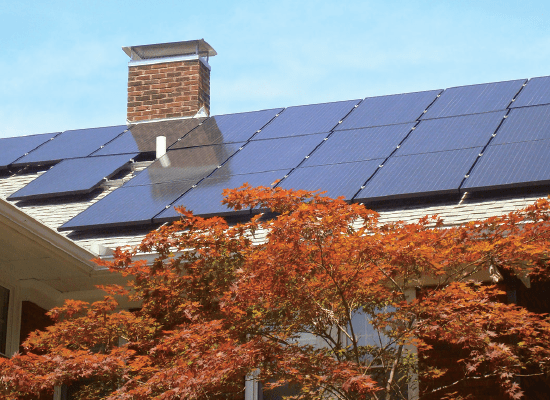
The roof of my house was shaded by a very large silver maple. My family and I loved the tree, but if we were going to get to net-zero or net-positive energy, it had to go. It turned out to be a good move; unbeknownst to us, the tree was rather rotten inside. We planted a paperbark maple in its place, which will not grow high enough to shade the roof of the house.
I was not about to do the roof of my two-story house myself. Ty Newell suggested hiring New Prairie Construction to do the work. They had done the addition on the back of my house, and while they had not done any solar installations, they are smart and pleasant to work with. Led by Nick Gordon, together we installed 41 modules on the house, bringing the total up to 69 (17.6 kW). New Prairie went on to establish a solar photovoltaic division and has installed over 1,200 kW on about 150 homes in our community.
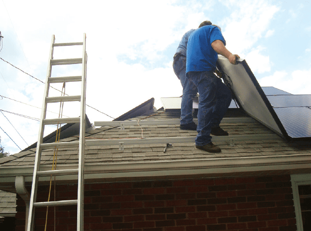
My main regret is the mounting system I used for the modules, which consists of long aluminum rails bolted to L-shaped feet standing on the roof, attached to the roof rafters with long screws. There are alternative systems in which the rails are unnecessary. The rails provide a good place for squirrels to build nests, and while they have not caused any damage so far, I worry that they will someday acquire a taste for electrical wiring. We used generous amounts of Flexible Seal under the feet, and thus far there have not been any issues with leaking.
Geothermal Heating and Cooling
The most efficient way to heat and cool your home with electricity is with a ground-source heat pump, also known as a geothermal system. In cooling mode, it is just a central air conditioner, but with the heat rejected to the cool (55°F) ground rather than to the hot outdoor air. The rejected heat is delivered to the ground via water (with some glycol added) pumped through vertical boreholes. In heating mode, the water extracts heat from the ground and delivers it to the heat pump, where its temperature is boosted and then delivered to the house via the existing ductwork. This is about four times more efficient than resistive heating. The cooling is about twice as efficient as a standard central air conditioner; in addition, some of the heat can be rejected to your domestic hot water rather than to the ground, thereby decreasing the need for water heating.
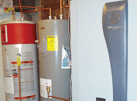
My basement utility room, which previously housed a natural gas furnace (and originally a coal furnace) was outfitted with a Waterfurnace 7 Series model, with a capacity of 5 tons, which is just right for my 2,500 square foot house. The far tank in the photo is a 50-gallon GE (air source) heat pump water heater (no longer available). This extracts heat from the air, thereby boosting its efficiency, and also dehumidifies, which is useful year-round. It is three times as efficient as an ordinary electric water heater. We do not condition our uninsulated basement, so we are not extracting heat from the living area. The gray tank in between the Waterfurnace heat pump and the GE water heater is in fact an ordinary electric water heater, but it is not plugged in. It merely serves as a storage tank for the warm water that is produced by the heat pump when it rejects heat to domestic water in cooling mode. The entire system is remarkably quiet; you cannot hear it on the first floor, even when you are standing directly on top of it in our kitchen.
The system was designed and installed by Jim Hall of Design-Air, who calculated that I would need a 5-ton system (corresponding to 1 ton per 500 square feet). It turned out to be a remarkably accurate calculation. The heat pump has variable capacity, and on the coldest days it will run at maximum and is able to keep the house at 72°F. I was astonished that it was even able to handle a -15°F day that we had on January 30, 2019—a polar vortex event. The system has a backup 15 kW resistive heating element, but I never use it. It is switched off, and I only switch it on if I will be away from the house for a few days in the winter, to ensure against loss of heating. This did happen once when a circuit board went bad, and I was alerted of the event by my smartphone.
At the time the system was installed, I also had dampers added to create two zones, one upstairs and one downstairs. This significantly increased our comfort. My main regret, which is correctable, is that I did not make my kitchen/breakfast room, which is in the addition, into a third zone, as its heating and cooling needs are very different from the rest of the first floor.
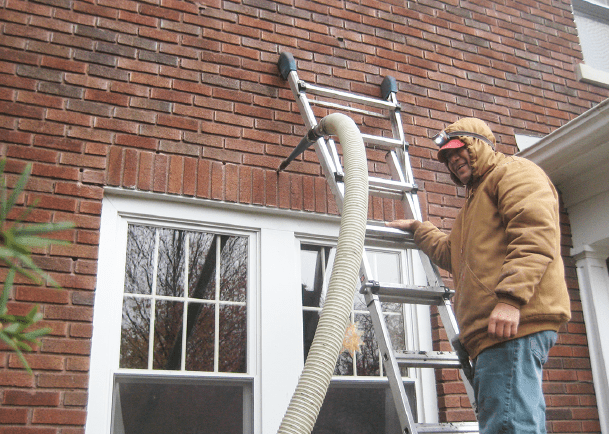
Weatherization
Our 1929 wood-framed, brick house was built with no insulation in the walls, and only a thin layer of rock wool in the attic. In 2006 we had 5 ½ inches of cellulose blown in under the floorboards of the attic, and the attic ductwork wrapped in insulation. We also replaced all the original, single-pane windows with Pella Architect Series double-pane windows. Despite these improvements, we still had a long way to go to achieve a good thermal envelope.
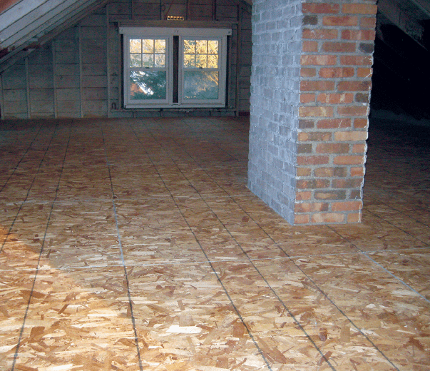
We hired Tim Ferris of Capital Weatherization to do an energy audit of our house. Using a blower door and infrared thermography, he found a lot of room for improvement. First, he discovered a gaping hole in our attic’s thermal envelope, which had been created inadvertently when the addition was added to the back of the house. After that was remedied, he built a raised floor in our attic and blew in 9 inches of loose-packed cellulose, bringing the attic up to R-49. He then blew 3 ½ inches of dense-packed cellulose (R-13) into our wall cavities, accessing the cavities mainly through the attic and the basement. Where that was not possible, he drilled 1-inch holes through the mortar joints and patiently blew in the cellulose from the exterior. He did not touch any interior walls. He then insulated and sealed the rim joist in the basement using closed-cell foam (R-13). Finally, he added weather stripping to the exterior doors and attached a 2-inch foam board to the back of the attic door.
Progress!
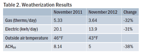
The results were dramatic (see Table 2). A second blower door test revealed that air-changes per hour at a pressure of 50 pascals (ACH50) had been reduced 38%. Our next utility bill reported that natural gas consumption was down 32% from a year earlier, despite the average outdoor air temperature being 3°F colder. To my surprise, electricity consumption was down just as much; I attribute most of this decrease to the furnace’s blower fan not being on as much, although some is also due to replacing a few lights with LEDs. Comfort was also increased dramatically. An unexpected side effect was increased sound insulation, a welcome benefit on our brick-paved street.
My main regret is that I did not add even more insulation to the attic ductwork. Those ducts are now under the new attic floor, but, using an infrared thermometer, I found that a significant amount of heat was penetrating the floor above the ducts. To stop the heat loss, I laid 2-inch foam boards on the floor overtop of the ducts. It would have been neater to do this under the new floor.
The Achilles heel of the thermal envelope is the sunroom. This room was originally unconditioned, but ductwork was extended to it during a major remodel in the 1950s. Tim used closed-cell foam to improve the crawlspace wall insulation (R-13), but the room was still uncomfortable in the winter. In 2016 I replaced the original single-pane windows with triple-pane Pella casement windows (R-5) and had cellulose blown into the ceiling, along with adding a 4-inch foam board on the roof, bringing the ceiling to R-50. This reduced the ACH50 of the house another 6%, to a value of 4.7. I was still not satisfied with the comfort of the room, so in early 2019 I had Tim rip out the fiberglass insulation under the floor (presumably added in the 1950s remodel) and replace it with four inches of closed-cell foam (R-20). He also added more foam to the crawlspace walls (R-20). I have spent much more money per square foot on this 130-square-foot room than any other, yet it is still the least comfortable. I think the main problem is the walls, which contain fiberglass insulation (presumably from the remodel) and cannot be easily retrofit.
Lights and Appliances
I replaced my fluorescent bulbs with LEDs as they became more affordable, taking advantage of incentives whenever I could. It is remarkable to look back and see the progress that has been made in lighting. For example, in January 2013 I bought a box of 20 LEDs that had won the “L Prize”, award ed by the Department of Energy for being the most efficient. Including incentives, these 10W (60W equivalent) bulbs cost $15 each. Today you can get an equivalent bulb, using only 8.5W, for about $1. I have about 75 bulbs of various shapes and sizes in my house, and all but a few are now LEDs. These bulbs were installed over a period of years, so the energy savings accrued gradually.
The most efficient light is one that is on only when necessary. We had a bad habit of forgetting to switch off our basement lights. This problem was solved by installing a timer switch in the laundry room and an occupancy sensor in the play area. We also added a timer switch to the kitchen exhaust fan.
Since I already had an electric stove, the last major appliance that I had to replace was the gas clothes dryer. Once that was done, I could cancel my natural gas service. I rented an electric dryer, waiting for a heat pump clothes dryer to come on the market in the United States. I thought I was the first person in my community to own the new Whirlpool heat pump clothes dryer, but soon learned that Ty Newell had beaten me to it. It is twice as efficient as an ordinary electric clothes dryer.
The other two electric “appliances” we added are our Chevy Volt (a plug-in hybrid) and our Tesla Model X. We only use the Volt (40-mile range) locally, so the gas engine is rarely used. The Tesla Model X (260-mile range) is used locally and for road trips. We produce enough energy to support the cars’ local travel. We are obviously not providing the electricity to recharge the Tesla on road trips. I could go on further about the cars but suffice it to say that once you own an electric car, you will never want to drive a gasoline powered car again.
Performance
Although it varies from year to year, on average we have made about as much energy as we have used over the past five years. The figure below shows the amount of electricity imported from and exported to the grid on a monthly basis throughout 2017, a typical year. In the summer we produce much more energy than we need, while the reverse is true in the winter. In 2017 we exported 14,400 kWh and imported 13,440 kWh, so we were a net exporter of energy. Since we are on net metering, we only pay for the excess that we import each year.
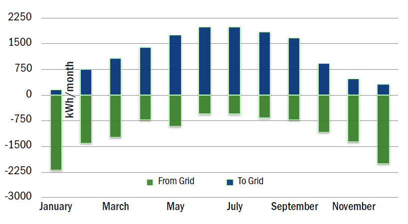
You may be wondering why I am not telling you how much energy we produced/used in addition to how much we imported/exported. The reason is that I don’t know. The solar monitoring system should be able to tell us our production (from which we could calculate our usage), but when the heat-pump compressor is working hard in the winter it interferes with the powerline communications and no data is recorded. The import/export data, on the other hand, is obtained directly from my electric meter.
Editor’s Note: This article was originally published in the BPA Journal print edition in Spring 2020. Since then, author Scott Willenbrock has installed two Tesla batteries, dealt with unruly raccoons wreaking havoc on his roof, and has gained insight on how his solar array is doing after 10 years. Stay tuned for his latest article on his home, set to publish in January 2024.
Related Articles

How One Maine Homeowner Turned His 101-Year-Old Home Into a Haven

Top 3 Trends: How Energy Efficiency Changed in 2023
Colonial Solar House

Stay Updated
Sign up for our mailing list to stay updated on all things home and building performance.
"*" indicates required fields
By submitting this form, I understand I am subscribing to an email list to receive ongoing communication from BPA.